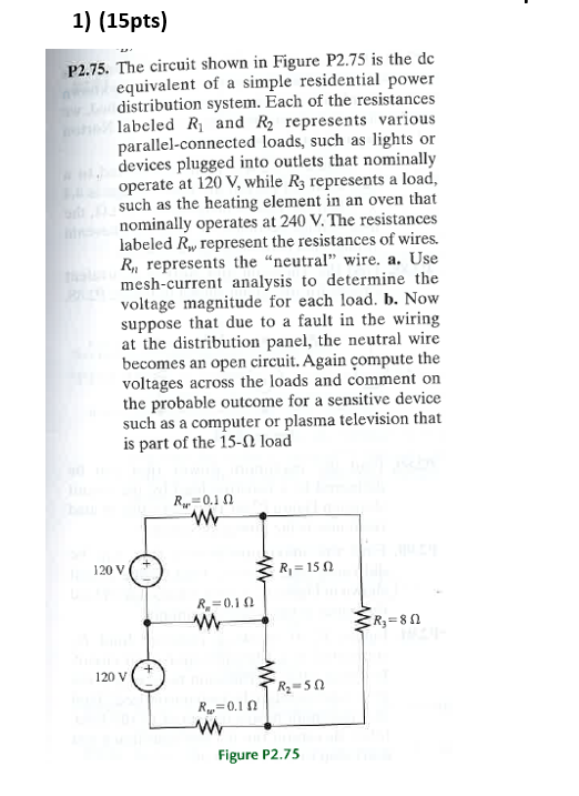
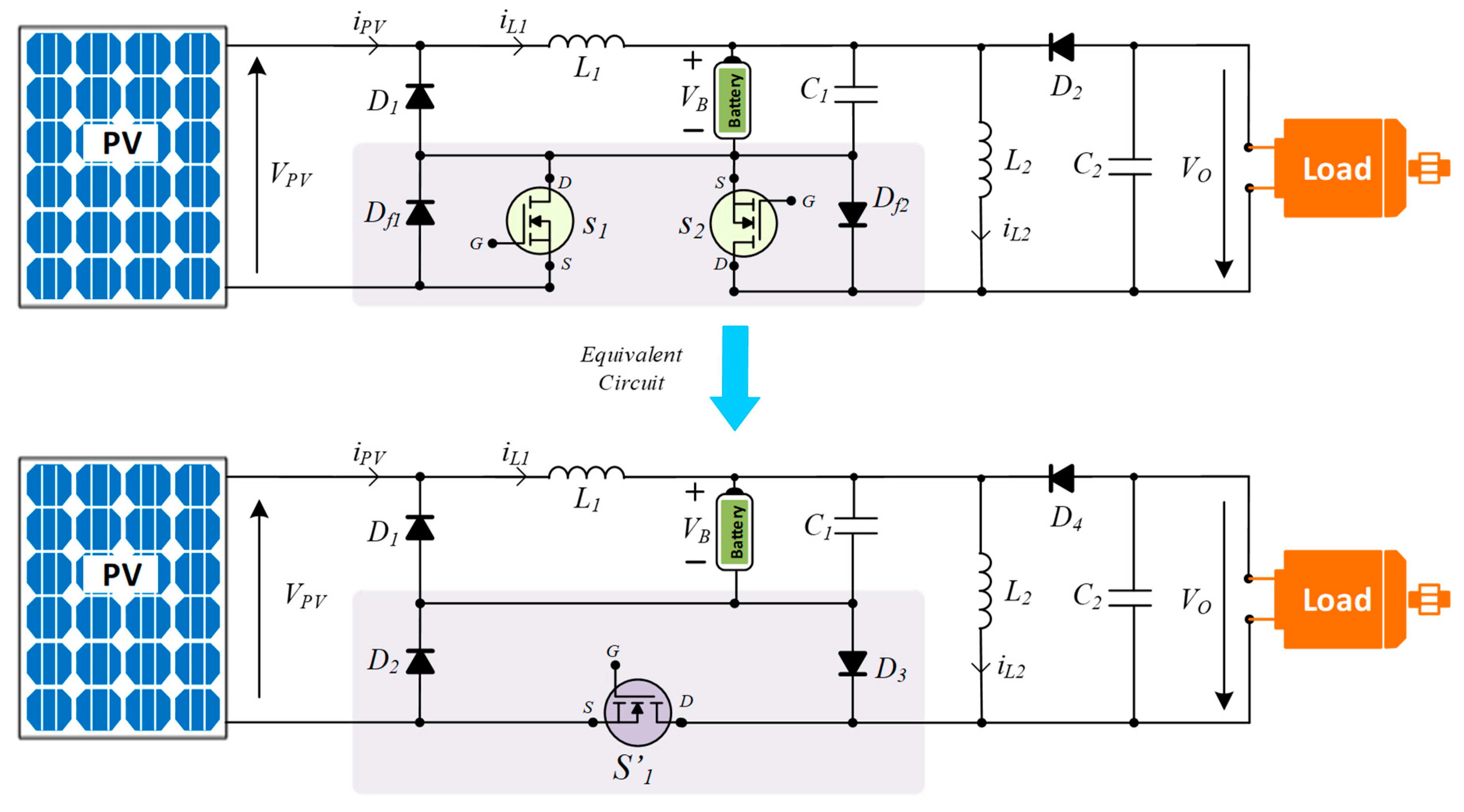
A Circuit System Is Given In Figure 211
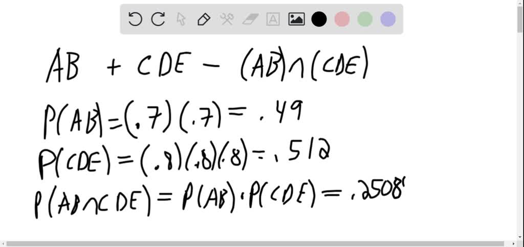
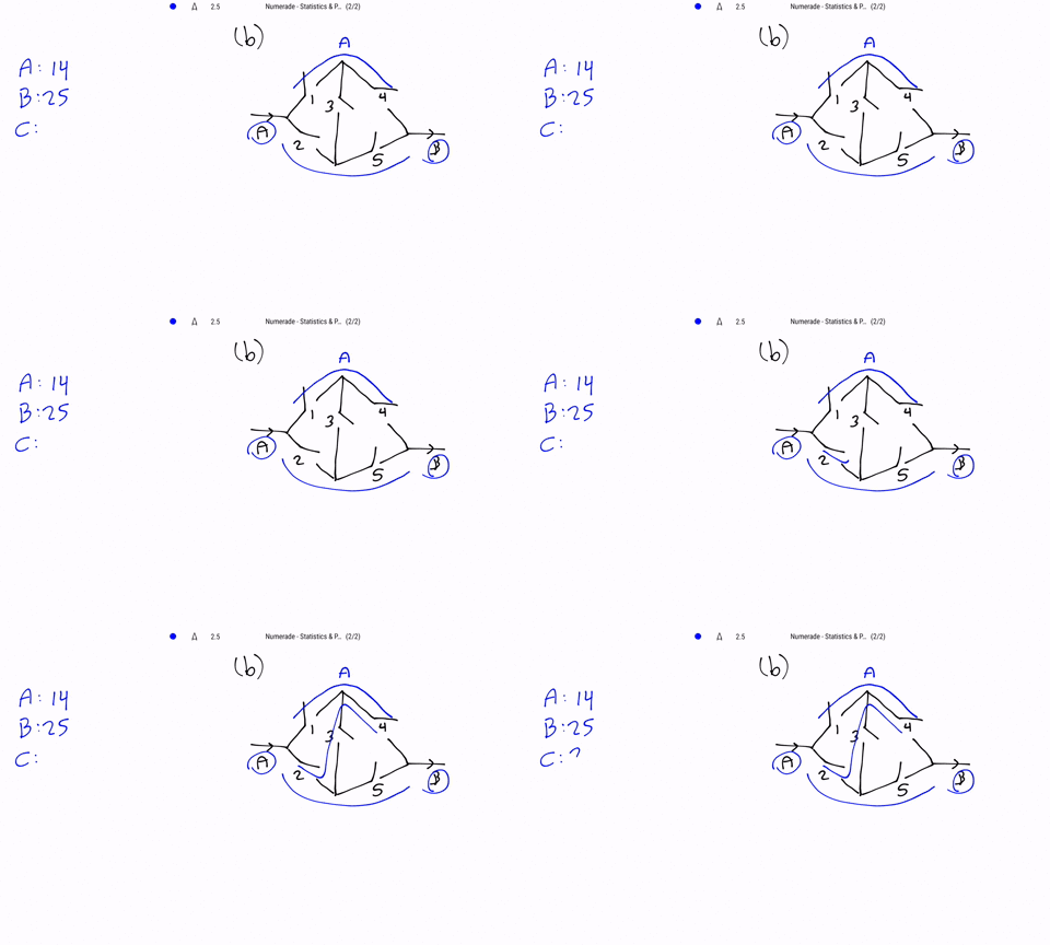
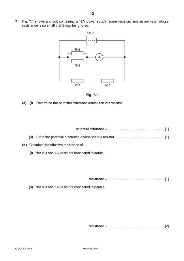
A circuit system is given in figure 211. A massspring system is shown in Figure 212. Selection of base quantities. B Given that the system works what is the probability that the component A is not working.
IA vV PIV W Direction 1 15 20 300 A to B 2 -5 100 -500 B to A 3 4 -50 -200 B to A 4 -16 -25 400 A to B 5U. Equivalent circuit obtained when a voltmeter is used in the simple voltage divider circuit. The system generators buses and transmission lines is protected by six overcurrent relays R.
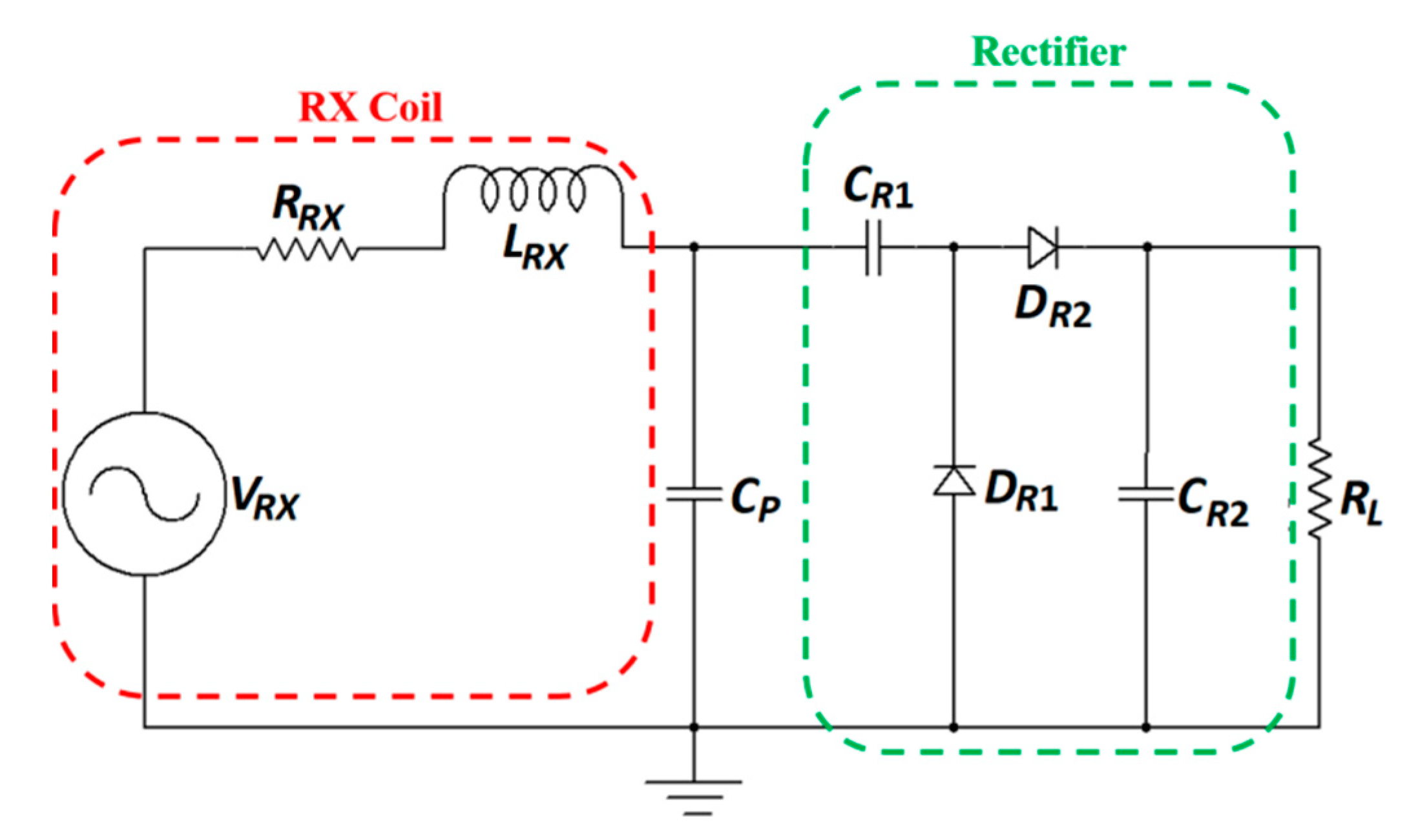
ÎThe figure shows the current and emf of a series RLC circuit. I or R1 8 8 R1 i 8 R 2 2 i i 2 or R 2 8 8 R2 2 i a i 2 A. The op-amp circuit is in the inverting amplifier configuration and so its transfer function is given by the ratio of impedances with Z RCs in the numerator position.
The output is related to the inputs by the equation. The one line diagram with the data is considered as shown in figure. 1 Increase R 2 Decrease L 3 Increase L 4 Increase C Current lags applied emf φ 0 thus circuit is inductive.
The circuit shown in Figure P53-3 has two inputs v s and i s and one output i o. B the resonant frequency cor. Mohammed Tawfeeq Problem 1.
A RC parallel op-amp circuit. Chapter 8 Solution 4. Determine the value of R2 and of the current i.
The CMOS switch in the sample and hold circuit has a low impedance when turned On and a. A circuit system is given in Figure 211.
Academiaedu is a platform for academics to share research papers.
An alternating voltage is given by v 75 sin 200πt - 025 volts. Determine the value of R2 and of the current i. Assume the components fail independentlya What is the probability that the entire system worksb Given that the. V S V. B Given that the system works what is the probability that the component A is not working. For simplicity we will ignore any damping by assuming that the spring is ideal and that there is no friction due to wind resistance. Equivalent circuit obtained when a voltmeter is used in the simple voltage divider circuit. Assume the components fail inde-pendently. A Nichols chart is given in Figure E914 for a system with Gc jÏG jÏ.
In section 21 an RC circuit with only a discharging capacitor was examined. Either 1 Reduce X L by decreasing L or 2 Cancel X. A circuit system is given in Figure 211 Assume the components fail independently. An alternating voltage is given by v 75 sin 200πt - 025 volts. The output is o 045 A when the inputs are i i s 025 A and v s 15 V. Voltage is given Vs10V time is given 0t2 R1 MΩC1μF10-6F question_answer Q. Assume the components fail independently.

















Post a Comment for "A Circuit System Is Given In Figure 211"